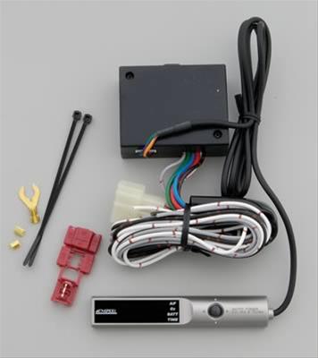
ELECTRONICS TECHNOLOGY Product Features Parts List Be sure to check the contents before attempting installation. Please notify your dealer of purchase for any missing or broken parts BEFORE attempting installation. Instruction Manual Control Unit Relay Unit Zip Tie Double Sided Tape Control Unit Fitting Splice Electro-Tap Serial Number Installation Procedures Vehicle Specific Chart Instruction Manual Installation Diagram Key Swich Vehicle Specific Harnes Sold Separately Version Information Please Relay APEXERA Co.,Ltd. http://www.apexera.co.jp Installing the Relay Controller Head office 1-17-14 Tanashioda,Sagamihara-city Kanagawa,229-1125 JAPAN ph: +81-42-778-3991 fx+81-42-778-4495 USA office A’pex Integration,Inc. 330W Taft Orange,CA.92865,USA ph : (714)685-5700 fx : (714)685-5701 (Glay Wire) O2 Sensor Signal(White Wire) Ground(Black wier) Engiine ECU Ground (Black Wire) When not using O2 Sensor Signal. Safety Precautions For safe use of this product, be sure to read the Safety Precautions. Keep the manual in a safe place after use for future reference. We have included these warnings to protect the user and dealer from unnecessary harm. These points have been marked throughout this manual by SIGNAL WORDS. Please refer to the table on the left for a glossary of term meanings. Perking Brake Switch Be sure to shut off the engine when sleeping inside the vehicle Never leave the vehicle while the engine is running This product is designed for domestic use only. It must not be used in any other country. GLOSSARY Display Meanings Failure to do so may result in Failure to do so may result in exhaust poisoning This could lead to accidents How to use the Electrotaps (Parking Brake Switch) WARNING death or severe injury to the user and others. Failure to do so may result in light injury to the user and others or product and engine damage. Failure to do so may result in product and engine damage. CAUTION PLEASE Be sure to secure this unit in a safe location away from the driver . Failure to do so may lead to accidents. Do not expose the unit to excessive shock. This could lead to unit malfunction. Never use this unit on a vehicle that is not intended for use. Insert wire Insert wire to be tapped Securely fasten with plier How to Splice the Wire We cannot guarantee proper operation of this unit on non application vehicles. This product should ONLY be installed by a professional installer. Installation requires past experience to prevent damage to the unit and vehicle. Discontinue use of this product immediately if any unusual odor or smoke comes from the unit. Failure to do so may result in electrical shorts and potential engine fire. Never disassemble tamper with this unit. or Always connect brake wire. the hand Please in tall with recommended harness. our Failure to do so may lead to accidents. This could lead to serious injury. If you have any inquiry for the harness please contact to your shop. Be sure that the unit has been properly connected when selling the vehicle. Also, be sure to provide the instruction manual to the new user. Please Do not use this product for any other purpose than the one listed in this manual. We are not responsible for any damages or injuries incurred from improper usage of this product. Never operate while driving. this unit Failure to do so may lead to accidents. Do not leave the engine running in closed garages or sealed areas. Failure to do so may lead to exhaust fume poisoning. Considerations Remote Door Lock Systems and Adjustable Steering Columns may not function properly after installation of this unit. Be sure to turn AUTO LIGHT systems OFF. Failure to do so may cause the lights to stay on after the engine has been shut off. This may kill the battery. Be sure to test unit operation and safety wire operation after installation. Checking the Safety Switch Parking Brake Switch Mounting the Control Unit Operation To activate Setting Mode… Hold the knob to the RIGHT Turn the TIMER OFF when not in use. To turn the TIMER OFF… Hold the knob to the LEFT After setting… Hold the knob to the LEFT How to Set To enter the setting mode… Activate the knob either UP or DOWN Set the minimum warning battery voltage Choose between 10.0V 15.0V in 0.1V increments To turn the TIMER back ON… Hold the knob to the LEFT Hold the knob to the RIGHT Hold the knob to the RIGHT How to set… Display Parameters A/F ratio Sensor Voltage Battery Voltage Countdown time To activate Setting Mode… Hold the knob to the RIGHT Once setting is complete… Hold knob to the LEFT This will return to the Display Mode Procedure Tilting knob to RIGHT or LEFT will change the range of A/F , O2 data (see Table1) To turn engine OFF during a TIMER countdown… For Calculation Mode Manual or Auto Hold the knob to the LEFT Hold the knob to the RIGHT Hold the knob to the RIGHT To toggle between A/F ratio O2 Sensor Voltage Battery Voltage After Idling Time, Activate the knob either UP or DOWN Display Selection How to Set Select Calculation Mode Hold knob to the RIGHT After setting… Hold the knob to the LEFT Changing the after idling time during TIMER countdown… Tilt knob UP Tilt knob DOWN After Idle Time O2 Sensor Voltage Manual Mode Hold Auto Mode If display looks like below,The unit is in Auto Mode A/F Ratio Battery Voltage If display looks like below,The unit is in Manual Mode To enter the setting mode… Hold the knob to the RIGHT How to set… Activate the knob either UP or DOWN Minute Second sec sec sec sec sec sec min min min mi min min min min min min Sec sec MAX Countdown Auto Calculation MIN Countdown Value Rate Value This sets the maximum amount of idle time. Value denotes MINUTES. Please choose between 1 min 8 min This sets the auto calculation rate of the Timer. There are three modes, H” High “n” Normal “L” Low This sets the minimum amount of idle time. The vehicle will always idle for at least this amount of time. Choose between 0~60 seconds in 10 second increments. Once setting is complete… Hold the knob to the LEFT Procedure Tilting knob to RIGHT or LEFT will change the range of A/F , O2 data (see Table1) If the O2 sensor has not warmed up enough, will flash red and green. Once the O2 sensor warms up, the display mode will initiate. Parameters that can be Set A/F ratio according to O2 Sensor Voltage O2 Sensor Voltage according to A/F ratio Minimum Battery Voltage Warning Countdown Time When the A/F reaches over 10.0, will flash red. Select When the A/F goes under 20.0 will flash green.
Instruction Manual
A turbo timer is a device designed to keep an automotive engine running for a pre-specified period of time in order to automatically execute the cool-down pe...